Printable Enclosure tutorial · Part 4 of 7
Part cards and EasyPrint
Add a parts list to each step, a part card for every part, and EasyPrint, so an end user can print the whole enclosure.
Tutorial part 4 of 7 in the Printable Enclosure series. Give end users everything they need to print the box themselves.
- Audience: Authors who have finished Text and Image pages.
- Before you begin: The Printable Enclosure manual at version
1.2.0, open in the editor. - Starting point: A manual that opens with a safety note and an image of the finished box, followed by five 3D steps and closing instructions.
- End result: The same manual with a parts list on each assembly step, a part card for each of the four parts, and a Part Cards panel in the end-user view. You will publish it as a new version.
What we are improving
Part 3 left one thing on the list:
- An end user who wants to print the box still has no way to get the parts.
The enclosure was designed so that every part prints without support material, which makes it a nice model to practice this on. We will be using three tools you haven't touched yet:
- End User Parts, to give each part its own part card.
- Required Parts, to say which parts each step needs.
- EasyPrint, so an end user can open a part straight in the slicer.
None of this changes your steps or the model. If you want to go deeper on any of these, Parts, part cards, and EasyPrint covers them in full. Here we will just apply them to this one manual.
How each part prints
The STEP file holds every part in its assembled position, so some of them need to be turned over before printing. You will record this on each part card, so the end user doesn't have to figure it out on their own.
| Part | Lies on the print bed |
|---|---|
BaseTray | Its floor, with the tray upright |
Lid | Its top face (the one with the logo), upside down |
HingePin | Its flat side |
FrontLatch | Its closed end, so the latch stands on its end cap |
Keep this table handy, you will need it in step 3.
1. Make each part an End User Part
An End User Part is any part an end user might want to get their hands on. For the box, that is all four.
- In CAD Hierarchy, select
BaseTray, then select Define. You can also drag the part into the End User Parts area instead. - Repeat for
Lid,HingePin, andFrontLatch.
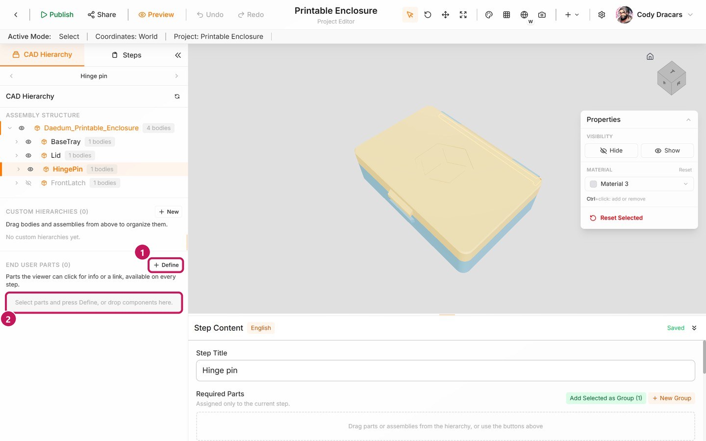
- (1) is Define.
- (2) is the End User Parts area, where you can drop a part instead.
When you are done, End User Parts reads (4). Each part now has its own card with a thumbnail and the words No link. The list is long enough that you may need to scroll it.
2. Set up each part card
A part card is what an end user opens to learn about a part. Every card in the list has a small card icon beside its eye. Select it to open Edit Part Card, then give each card a name and a description:
| Part | Name | Description |
|---|---|---|
BaseTray | Base tray | The tray, with two hinge knuckles on the back wall and the lower half of the latch rail on the front. |
Lid | Lid | The lid, with the center hinge knuckle, the upper half of the latch rail, and a lip that drops into the tray. |
HingePin | Hinge pin | A 3 mm pin with a head, pushed through the three knuckles. |
FrontLatch | Front latch | A clip that slides sideways over the two rail halves and holds the lid shut. |
Leave Link URL empty for now, we will come back to it in step 4. Select Save part card after you finish each one.
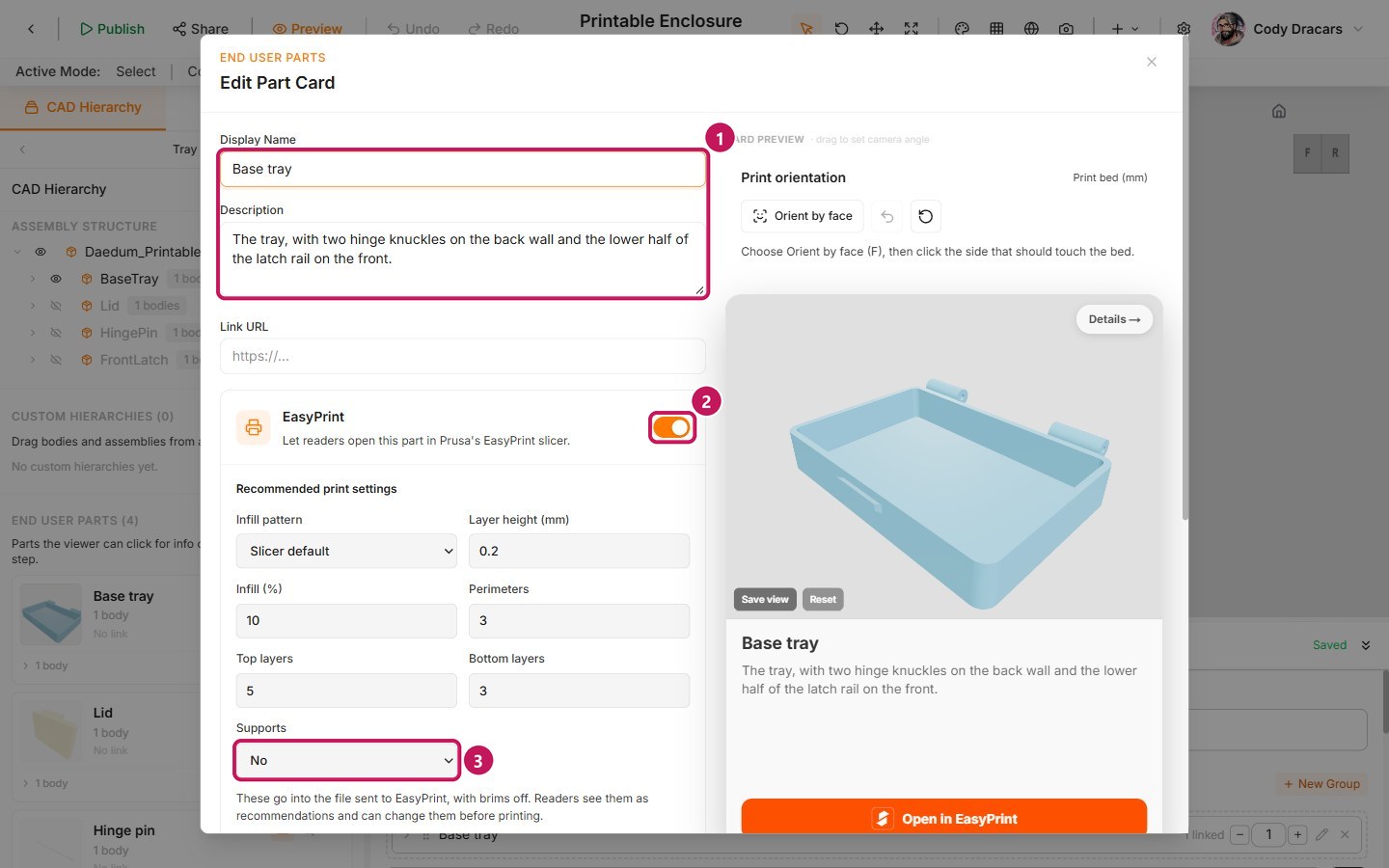
- (1) The name and description, which is what the end user sees on the card.
- (2) The EasyPrint switch.
- (3) Supports.
We will set up (2) and (3) in the next step. If you try to close the card after changing something without saving, Daedum will ask whether you really want to close it, so you won't lose work by accident.
3. Turn on EasyPrint and set the orientation
EasyPrint lets an end user open a part in Prusa's EasyPrint slicer without ever leaving the manual. In each card:
- Turn on the EasyPrint switch. Recommended print settings appear, already filled in for you.
- Set Supports to No, since the enclosure is designed to print without them. Leave the other settings as they are. An end user can always change them before printing.
- Under Print orientation, select Orient by face. The preview switches to a print bed. Click the face that should touch the bed (check the table above). The line under the buttons confirms it with Face placed on the bed.
- Select Done, then Save part card.
How much work each part needs depends on how it already sits in the model:
- Base tray: It already sits upright with its floor down, so there is nothing to click. Just select Done.
- Hinge pin: It already lies on its flat side. Select Done.
- Lid: It starts out standing on its edge. Click the large outer face with the logo, and the lid will lie flat with its hollow side up.
- Front latch: It starts out lying on its side. Drag in the preview to turn it until you can see the flat closed end (the end without the open rail slot), then click that face. The latch will then stand on its end.
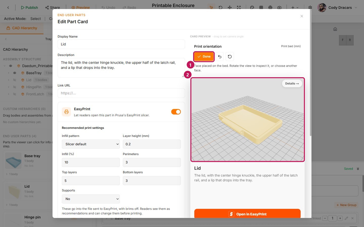
- (1) Done finishes the orientation step.
- (2) The bed preview shows the part the way it will print.
If the line reads Face aligned. Other geometry touches the bed first, you clicked a recessed face. Pick an outer face instead so the part sits fully on the bed. If you change your mind, Undo orientation and Reset orientation (beside Done) bring the old orientation back.
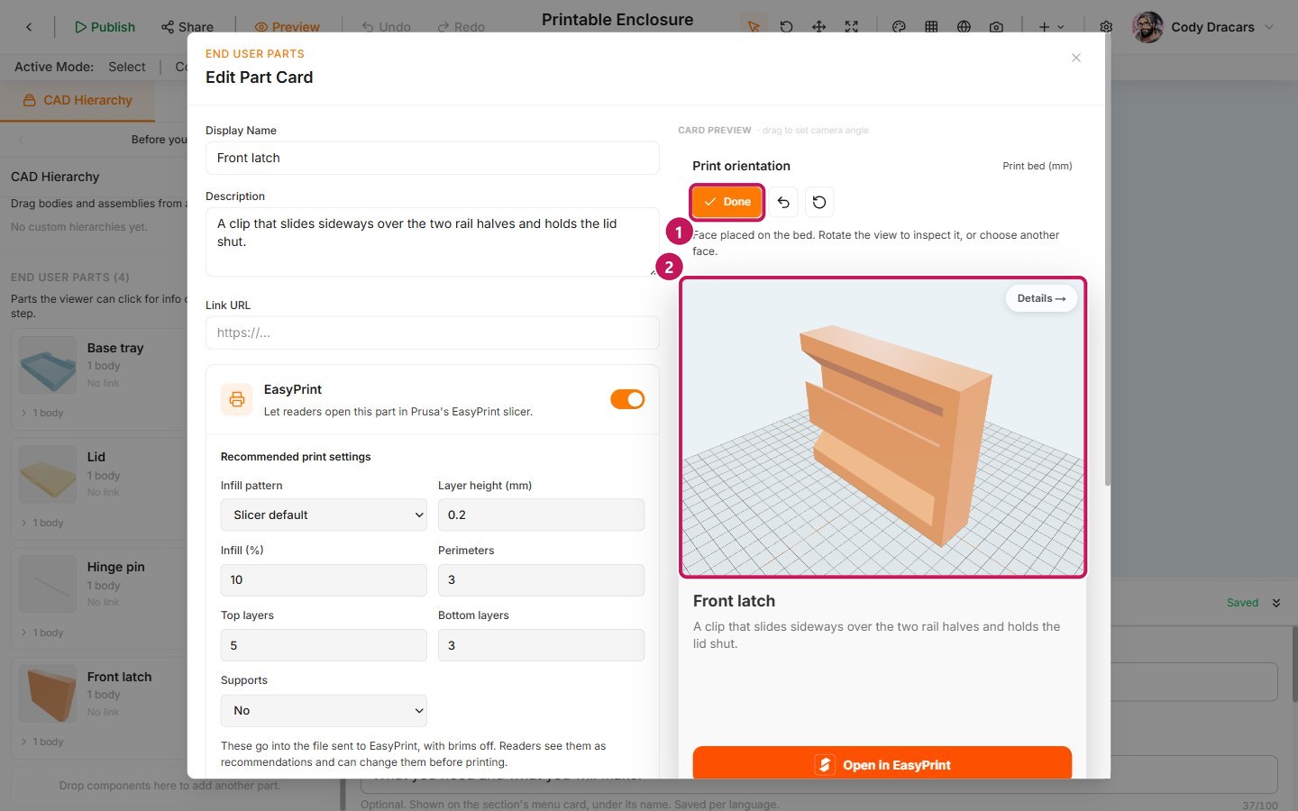
The latch takes the most turning. Once you have clicked its closed end:
- (2) The bed preview shows it standing on its end, with the rail channels running up its side.
- The line above it reads Face placed on the bed.
The orientation is only used for printing, so it won't change how the card looks. Once EasyPrint is on, its settings replace the free-text Print Settings on the card, so there is only one place that says how to print each part. EasyPrint is still a new feature, so it's a good idea to open at least one part in it and make sure it looks right.
4. Optional: link a Printables listing
If you publish the model on Printables, paste the listing link into the card's Link URL. Daedum recognizes Printables links, and the card will show a View on Printables button with the model's own preview and details.
You don't need a listing for this tutorial though. EasyPrint works fine without one.
5. List the parts each step needs
Required Parts is the list of what an end user needs for a given step. Because your parts are now End User Parts, you can drag one straight in and it keeps its card.
- Select the Tray step. Drag the Base tray card from End User Parts into Required Parts.
- Do the same on the other steps: Lid on Lid, Hinge pin on Hinge pin, and Front latch on Latch.
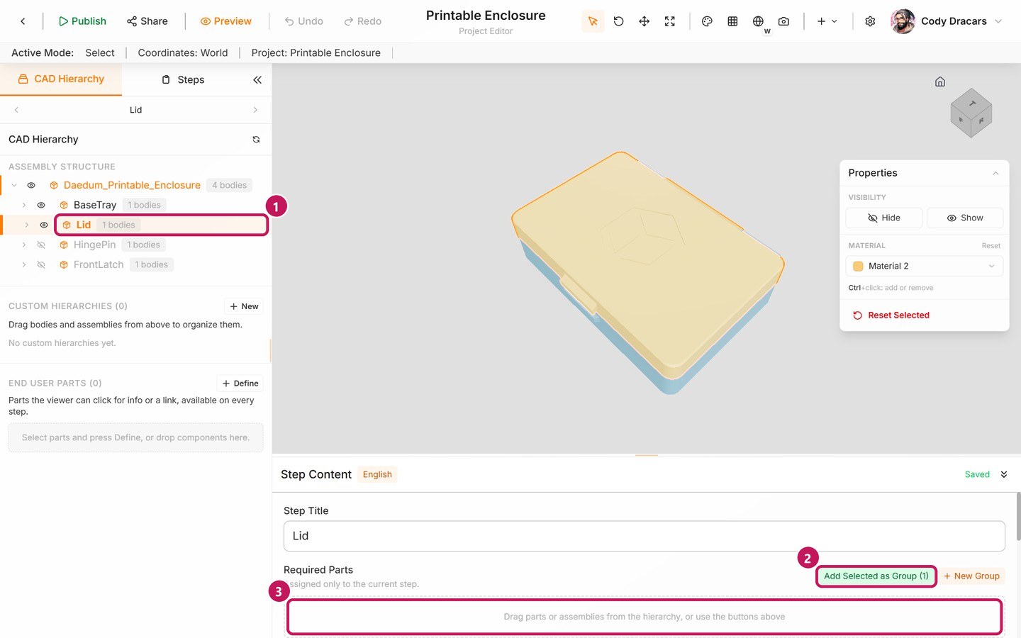
There is more than one way to add a part:
- (1) Select the part in CAD Hierarchy.
- (2) Then use Add Selected as Group.
- (3) Or drag it into the Required Parts area.
The entry takes the card's name and reads 1 linked, with a quantity beside it. Each part is a single body, so the quantity is 1. Leave the Finished box step without a list, since it shows everything and doesn't need anything in particular.
6. Turn on the Part Cards panel
The parts list on each step only shows that step's part. To let an end user browse every part card in one place, turn on the Part Cards entry in the end-user view's navigation. It stays off until you do.
- Select Settings in the editor toolbar, then the Embed tab.
- Turn on Part Cards Panel, then select Save Settings.
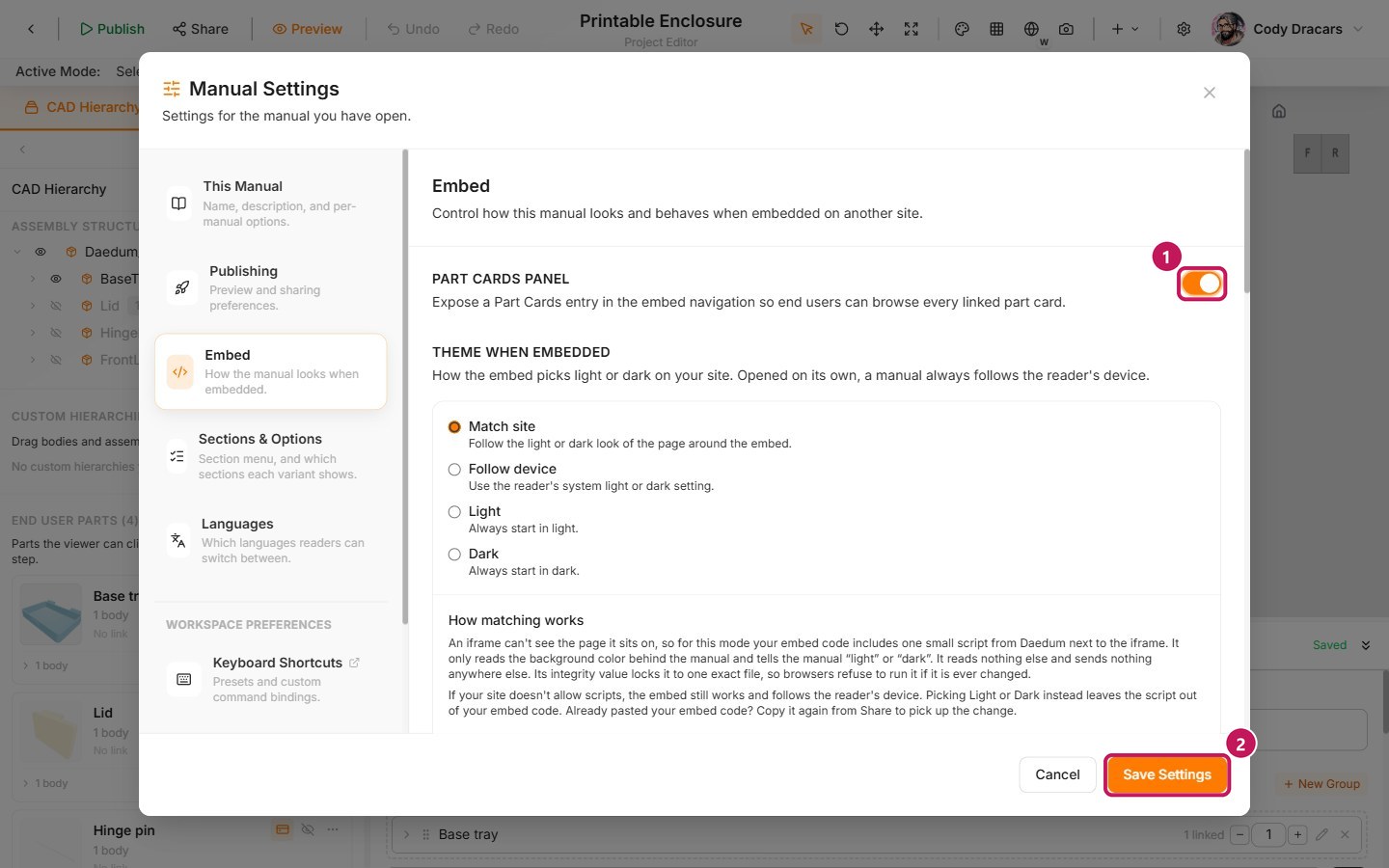
- (1) Turn on Part Cards Panel.
- (2) Select Save Settings.
7. Check the manual as an end user
Select Preview (Ctrl+Alt+P), open the Tray step, and look at the panel on the right.
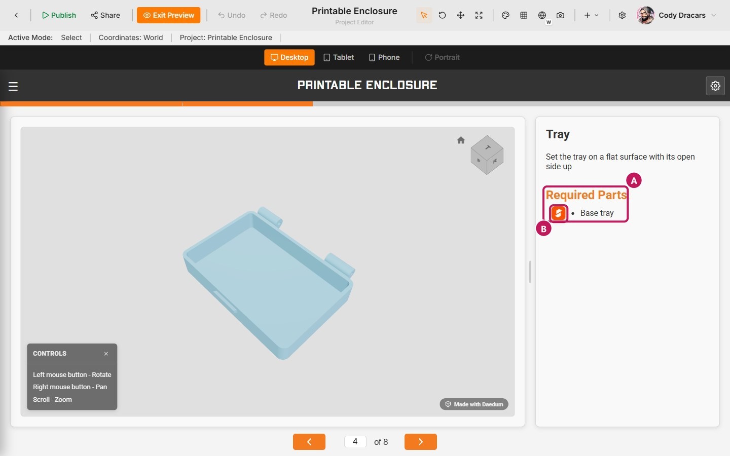
Under the instruction you will find:
- (A) A Required Parts list with the part's name.
- (B) An EasyPrint icon.
Use Next Step to walk through the manual, and check that:
- Each of the four assembly steps lists its part, using the name you gave it.
- Selecting the icon opens a box asking where to open the part, with Open in EasyPrint.
- The navigation menu (the three bars at the top left) ends with Part Cards.
Now select Part Cards to see them all together.
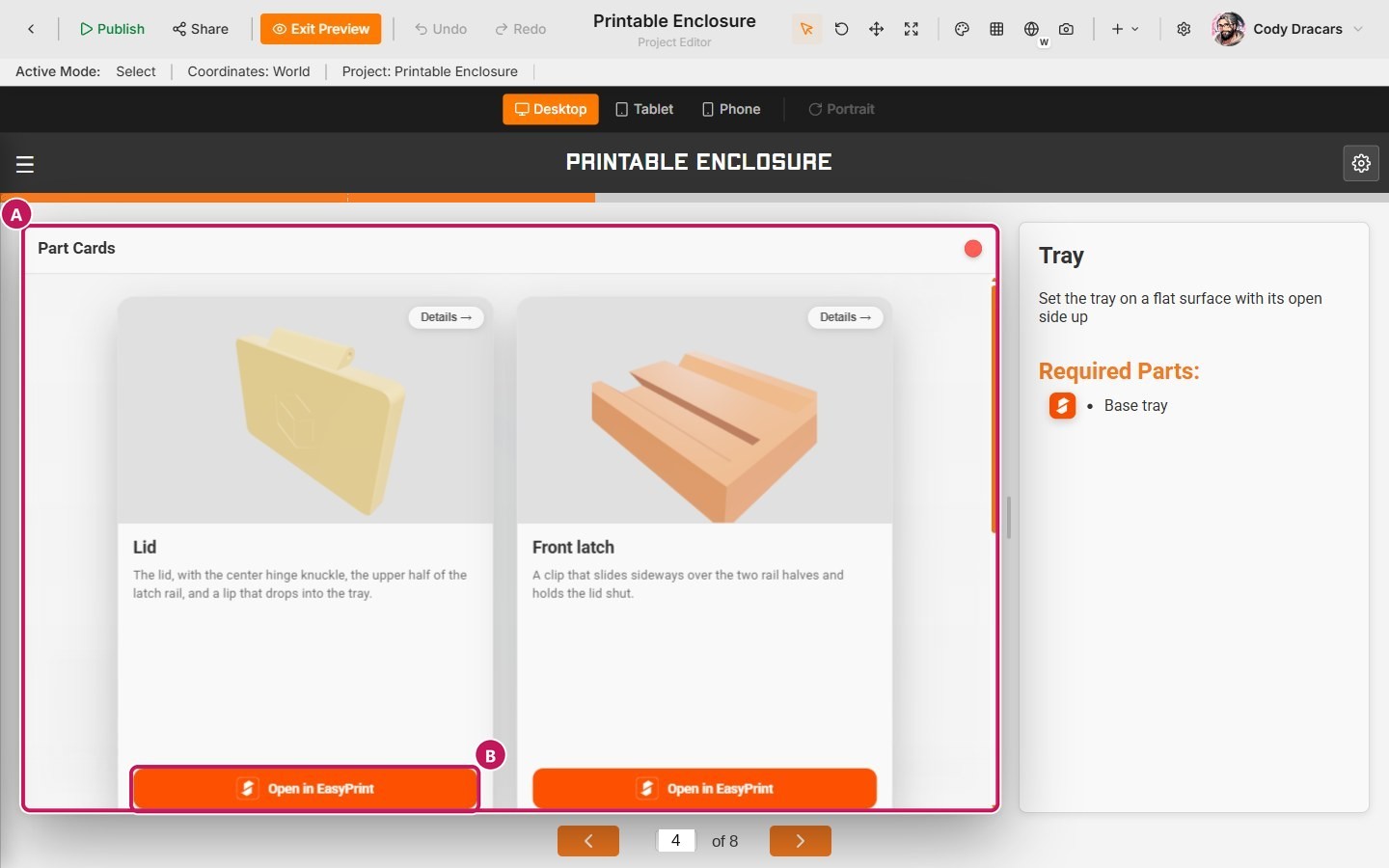
- (A) The panel shows a card for each part.
- (B) Each card has Details and Open in EasyPrint.
Select Details on a card and it flips over to show the description and the recommended print settings, including the Supports: No you set in step 3.
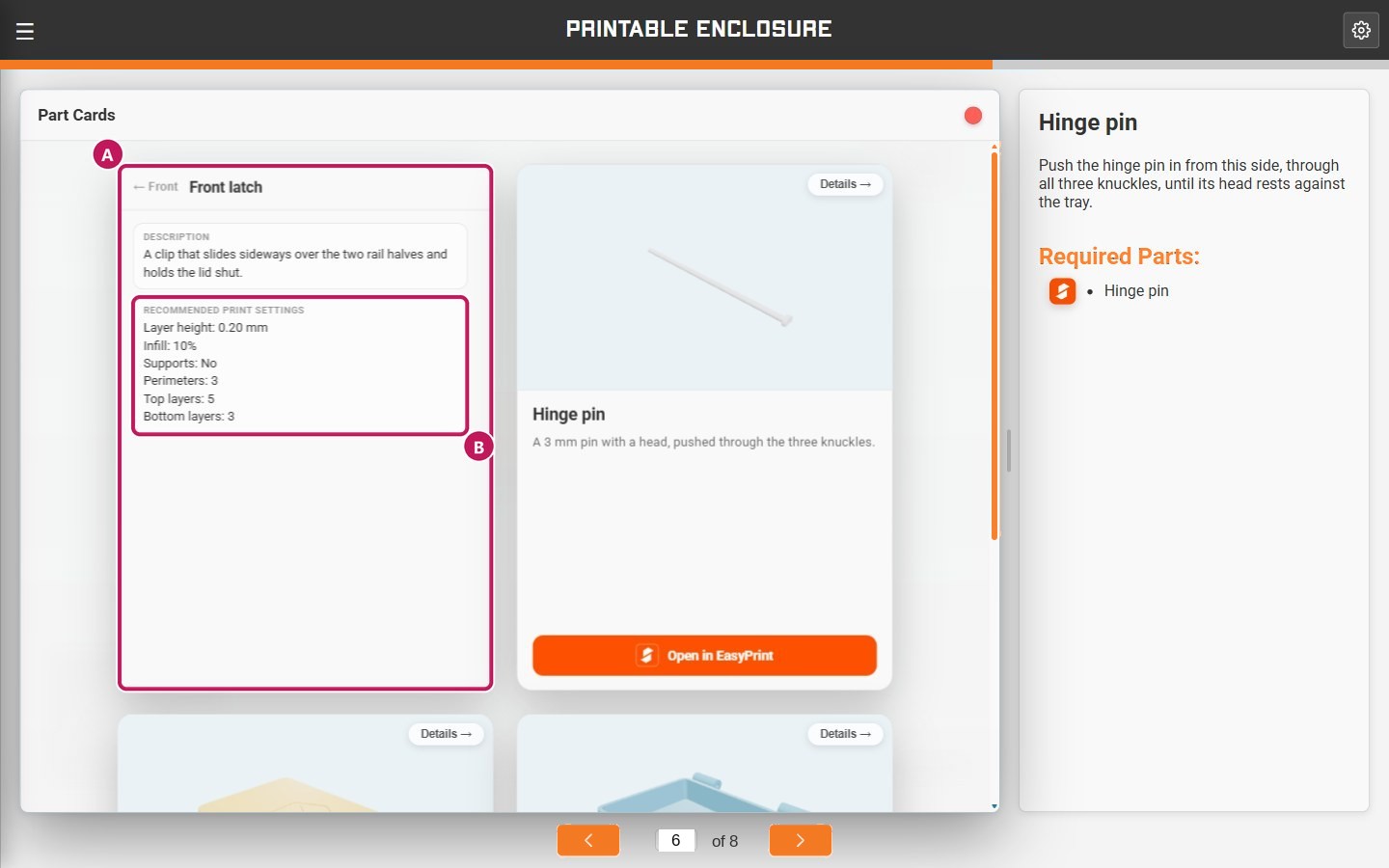
- (A) The card's description.
- (B) The print settings you chose, so an end user knows how to print the part before opening it in EasyPrint.
Select Exit Preview once everything checks out.
8. Publish the new version
As always, editing the manual doesn't change what end users see until you publish.
- Select Publish in the editor toolbar (
Ctrl+Alt+Shift+P). - Choose minor, which makes
1.3.0. - Add private release notes such as
Add part lists and printable part cards. - Select Publish.
Publish, version, and embed covers versions, visibility, and unpublishing.
What this manual does not do yet
End users can now see what each step needs and print every part. There is one thing still missing:
- An end user can only read the manual in English.
Add a second language is next: it adds Spanish and translates every step. If you are on a Professional or Commercial plan, you can take the optional Build options with Sections first. These guides cover the features on their own:
- Parts, part cards, and EasyPrint — custom hierarchies, part cards, and EasyPrint in full.
- Languages — adding languages and translating step text.
- Publish, version, and embed — versions, public links, and embeds.