Printable Enclosure tutorial · Part 2 of 7
Cameras, moving parts, and arrows
Give a step its own camera, move a part clear with Move Mode, and add arrows so end users see how the hinge pin and latch go on.
Tutorial part 2 of 7 in the Printable Enclosure series. Show how to attach the pin and latch with arrows in your manual.
- Audience: Authors who have finished Build and publish your first manual.
- Before you begin: The published Printable Enclosure manual from the part 1 (linked above), open in the editor.
- Starting point: Five steps that each show one more part.
- End result: An updated version of the manual showing attaching the pin and latch; as well as publishing as a new version of the manual.
What we are improving
When you walked through the first manual as an end user, a couple design choices were missing. This part of the tutorial fixes two:
- Every step opens from the same angle, so the hinge pin at the back is hidden behind the lid when it appears.
- Nothing shows how a part goes on. The pin and the latch simply appear in place.
But don't panic, setting this up is easy as we have already used one the tools in part 1 of the tutorial, and we will be introducing a few more. They include a saved camera, Move Mode, and a Straight Arrow. Nothing here changes the model or the other steps.
1. Give the hinge pin its own view
The pin sits at the back of the box, behind the lid, so the shared three-quarter view from the front hides it. Each step stores its own camera, so you can change this one step without touching the others.
- Open the editor and select the Hinge pin step in the Steps panel.
- Drag in the 3D view to turn the box half a turn, until you are looking at the back where the hinge is. Scroll to zoom so the box fills about half the view. Leave room on the left: in the next step the pin slides out that way, and it needs space to stay in frame.
- Select Set Initial Camera (1) in the toolbar, or press
Ctrl+Alt+C. Then select Save Camera (2).
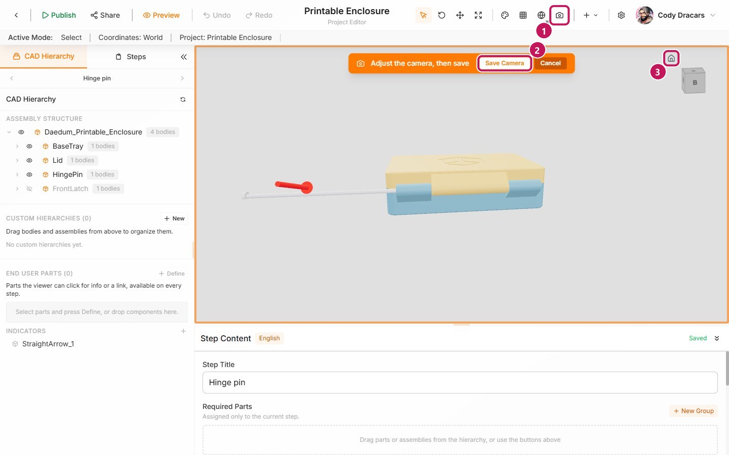
The Home Button (3) at the top right of the 3D view always returns to the saved camera, so you can move around freely while you work and snap back.
2. Pull the pin out of the hinge
An end user understands a fitting step faster when they see the part before it is fitted. Move the pin out so the step shows where it starts.
- In CAD Hierarchy, select
HingePin. - Select Move Mode (1) in the toolbar, or press
T. Three arrows appear on the pin, one for each direction. - Drag the arrow (2) that points along the pin (the red one) until the pin is clear of the knuckles. The arrows are thin, so press on the red arrowhead; if the view turns instead, you missed it. You can drag in several short pulls, because the arrows follow the pin.
- Select Select Mode (
V) and click an empty part of the 3D view to deselect the pin. PressingEscclears the selection too.
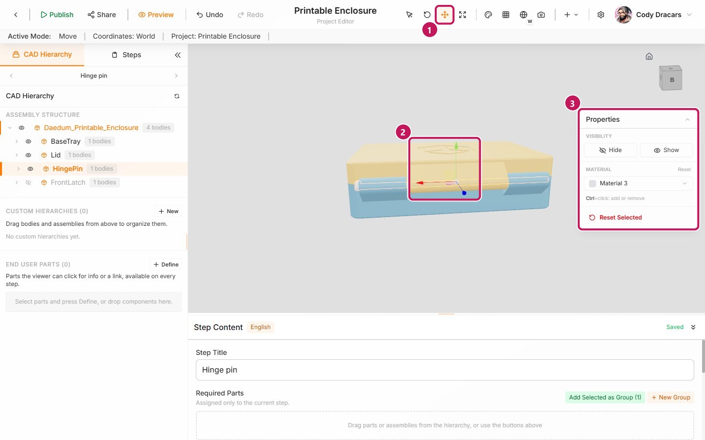
The pin is moved only in this step. The other steps still show it in place. If you overshoot, select Reset Selected in the Properties panel (3), or press Alt+R, and confirm with the red Reset button; that puts the pin back where the file had it.
3. Add an arrow that shows the way in
The pin is now floating beside the hinge, but nothing says which way it goes. To help say which direction it needs to go, we will add an arrow.
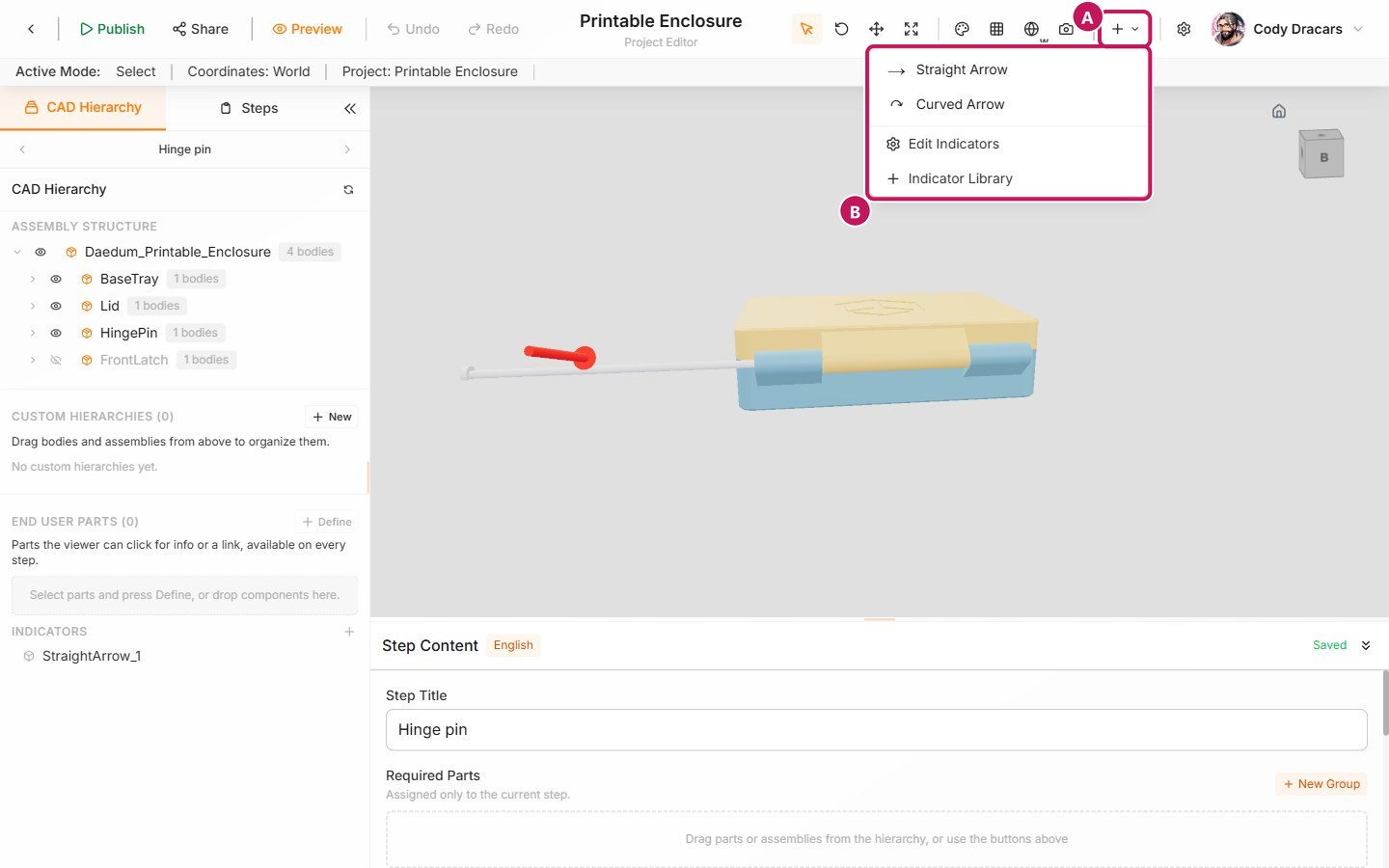
- Select Add Indicator (A) in the toolbar, then Straight Arrow (B). A bar at the top of the 3D view reads Click to place. Press
Escif you want to cancel. - Click the pin. The arrow points into the surface you click, so it will not yet lie along the pin.
- Select the arrow under Indicators in CAD Hierarchy. Use Scale Mode (
S, or the pinch/zoom icon on the toolbar) to shrink it: drag the small white square on the gizmo toward the arrow. Then use Rotate Mode (R) to turn it until it lies along the pin and points toward the hinge. The outer yellow ring turns the arrow flat against the screen, which is what you want here; the red, green and blue rings turn it around one axis each. - Select Select Mode (
V) and click an empty part of the 3D view to deselect it.
Rotating takes a little patience. If the arrow ends up at the wrong angle, select it and rotate again; you cannot damage anything. Snap rotation and movement explains how to make turns land on even angles.
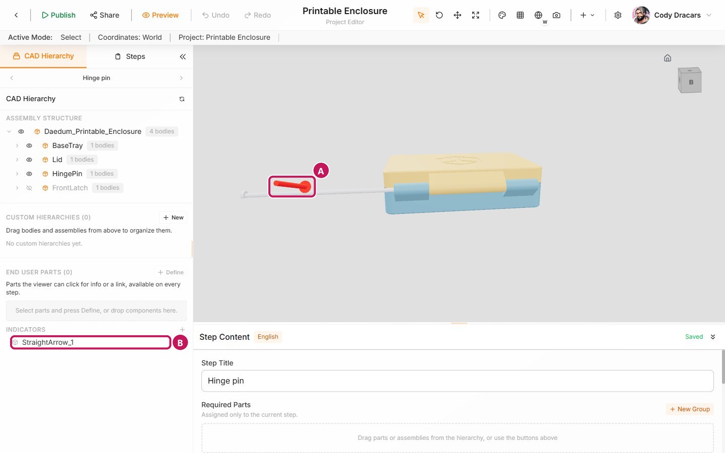
The arrow (A) also appears under Indicators (B), where you can change its color, Re-place Indicator, or Delete Indicator.
Update the instruction to match what the end user now sees. In Instructions, replace the text with: “Push the hinge pin in from this side, through all three knuckles, until its head rests against the tray.”
4. Do the same for the latch
The latch has the same problem: it appears in place, so an end user cannot see how it fits. It slides on sideways along the front rail.
- Select the Latch step.
- Select
FrontLatchin CAD Hierarchy, select Move Mode (T), and drag the arrow that points along the front of the box until the latch is clear of the rails. - Add a Straight Arrow on the latch, shrink it, and turn it so it points along the rail in the direction the latch slides on. Here the green ring does the turning: drag its handle around the ring, a little at a time, until the arrow runs along the front edge. Deselect it when you are done.
- Replace the instruction with: “Close the lid, then slide the latch sideways over the rail on the front, in the direction of the arrow.”
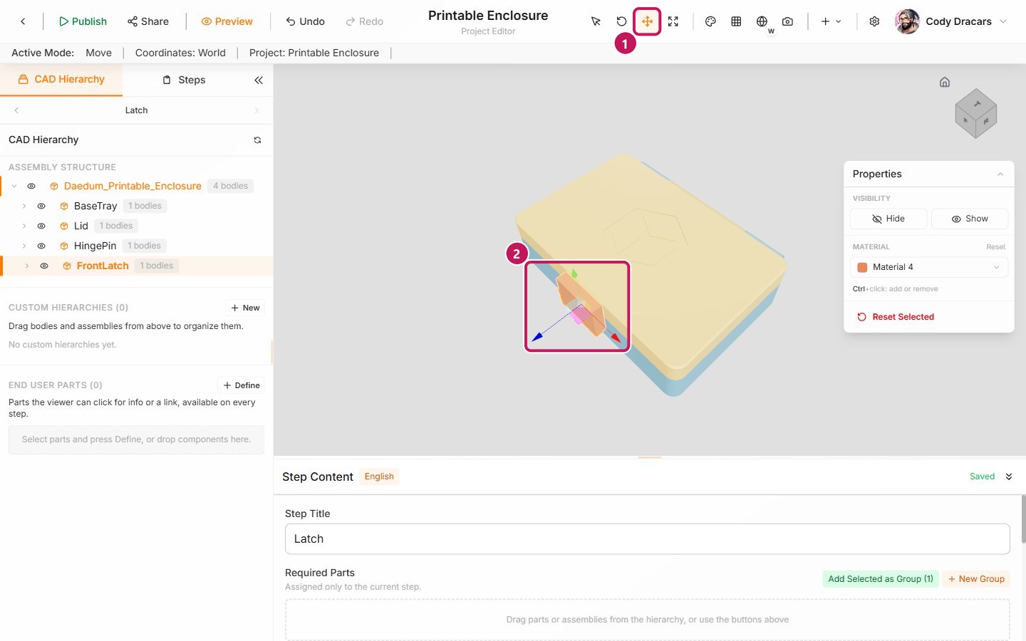
Move Mode (1) puts the arrows on the latch (2). The red one points along the front of the box.
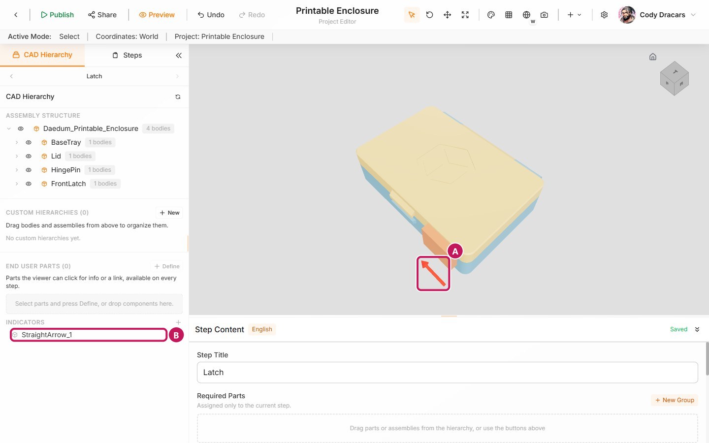
The arrow (A) points back along the rail, the way the latch will slide on. It is listed under Indicators (B).
This step keeps the shared three-quarter camera. The latch is on the front, which that view already shows.
5. Preview the end-user experience
Select Preview in the editor toolbar (Ctrl+Alt+P) and use Next Step to walk through the manual. Check that:
- the Hinge pin step opens from the back and shows the pin beside the hinge with an arrow;
- the Latch step shows the latch clear of the rail with an arrow;
- the other three steps are unchanged;
- each arrow points the way the part goes, not away from it.
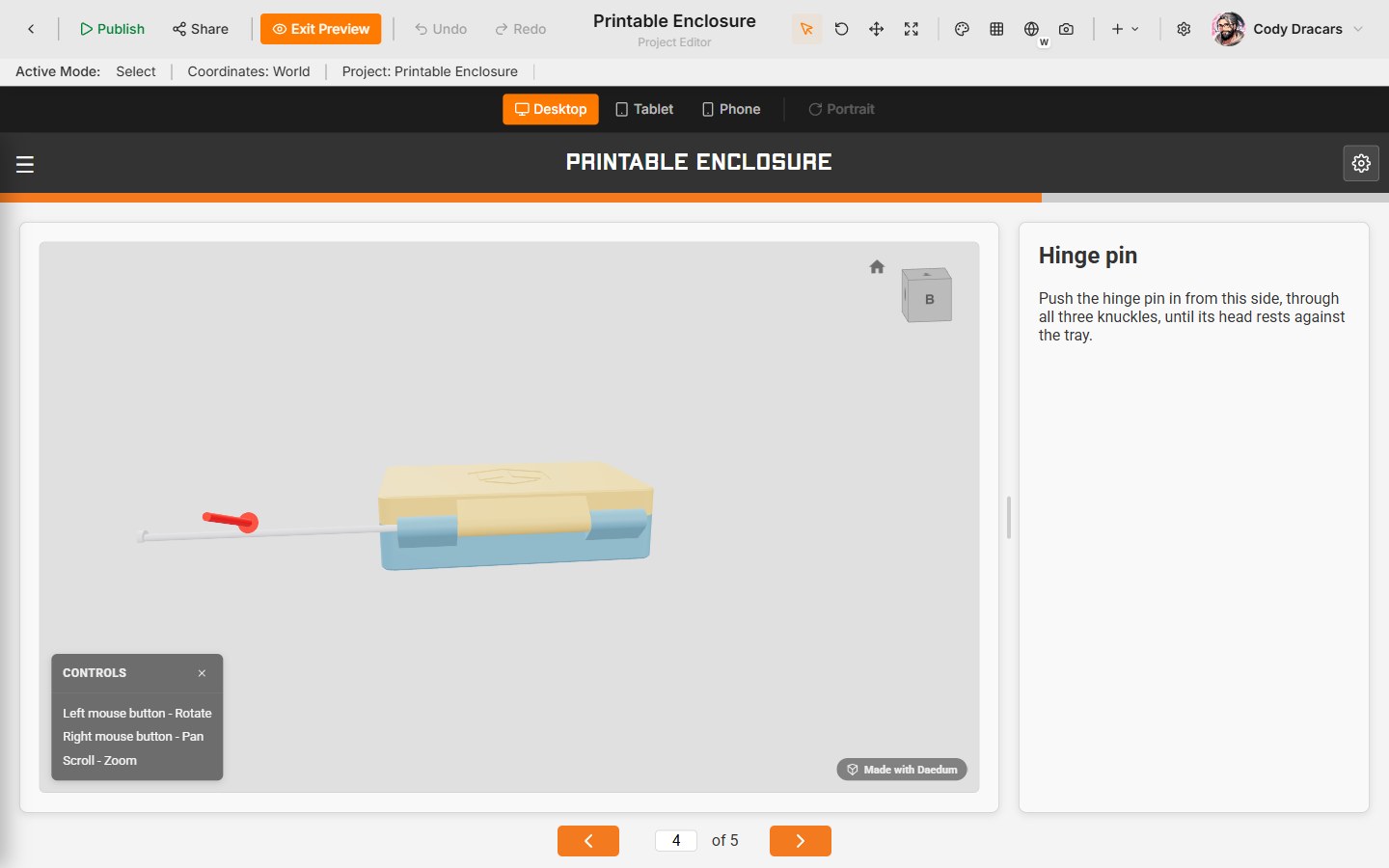
Select Exit Preview when both steps read clearly.
6. Publish the new version
Editing the working manual does not change what end users see. Publish the changes as a new version.
- Select Publish in the editor toolbar (
Ctrl+Alt+Shift+P). - Keep the suggested version for a small change. After
1.0.0, the dialog offers patch, minor, and major choices; choose minor for a visible improvement like this one, which makes1.1.0. - Add private release notes such as
Show the pin and latch going on. - Select Publish.
End users who open the manual's public address see the new version straight away. The old version stays in the Versions list on the manual page, so you can compare or hide it. Publish, version, and embed covers versions, visibility, and unpublish.
What this manual does not do yet
Alright! You have added step cameras and arrows to help guide the end user. What is still missing:
- The manual is all 3D steps. There is no introduction, no safety note, and no grouping into phases like preparation and assembly.
- An end user who wants to print the box still has no way to get the parts.
Text and Image pages is next: it adds a safety note, an image of the finished box, and closing instructions around the 3D steps. These guides cover the features on their own:
- 3D steps: visibility, cameras, and moving parts — cameras, moving parts, arrows, and procedure structure.
- Step types: 3D, Image, Text, and Section — Image and Text items.
- Publish, version, and embed — versions, public links, and embeds.