Features
3D steps: visibility, cameras, and moving parts
Use the editor to show and hide parts, save each step's camera, move parts, write instructions, and preview the end-user experience.
Some features on this page are paid. They are marked with a notice like this one right under their heading, so you can tell what works on the Hobbyist plan and what needs an upgrade. See Plans and limits for what each plan includes.
- Audience: Authors turning a converted assembly into a step-by-step procedure.
- Before you begin: The CAD source has finished converting and Open editor is available.
- Starting point: The editor is open with a step selected.
- End result: Steps in the right order, each with a clear instruction and a useful 3D view.
Open the editor
Once the STEP file finishes converting, select Open editor from the manual page. If the manual doesn't have any steps yet, Daedum creates the first one for you and selects it.
The editor really has two jobs:
- Organize the procedure in the steps list.
- Decide what the end user sees and reads on the selected step.
When it opens, you will see the converted assembly in the 3D view, the CAD Hierarchy or Steps panel on the left, and the selected step's content fields below. The idea is to pair one written action with one visible assembly state.
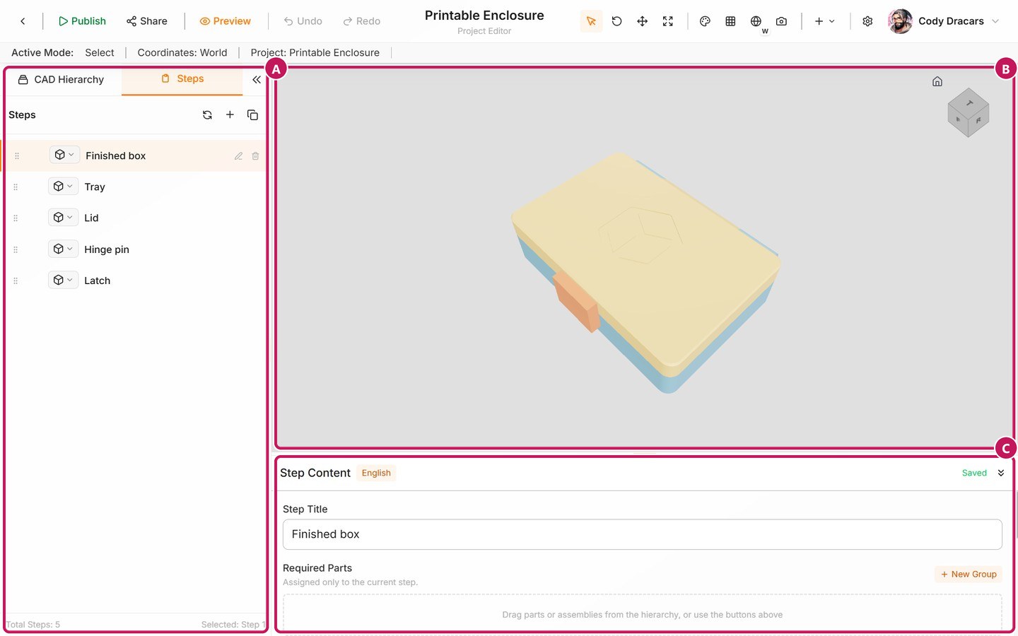
It helps to read the editor from left to right:
- (A) Procedure is the Steps tab of the left panel, and it is the order end users follow. The CAD Hierarchy tab beside it lists the model's parts. Sections group related steps, and the selected step is the one you are editing.
- (B) 3D assembly view is what end users see for that step. Frame the part that matters, and leave enough of the surrounding model that they can tell where they are.
- (C) Selected step is where you write the action and adjust that step's view controls.
Not sure where to start? Select the first step in Procedure, write one action in Selected step, then use the 3D view to make that action obvious.
If you are deciding between 3D Step, Image, Text, and Section, Step types: 3D, Image, Text, and Section walks through when to use each one.
Add a 3D step
Daedum creates the first 3D Step when the editor opens. To add another one, open Steps, select Add manual item, and choose 3D Step. The new step is selected right away, so you can jump straight into its title, view, and instruction.
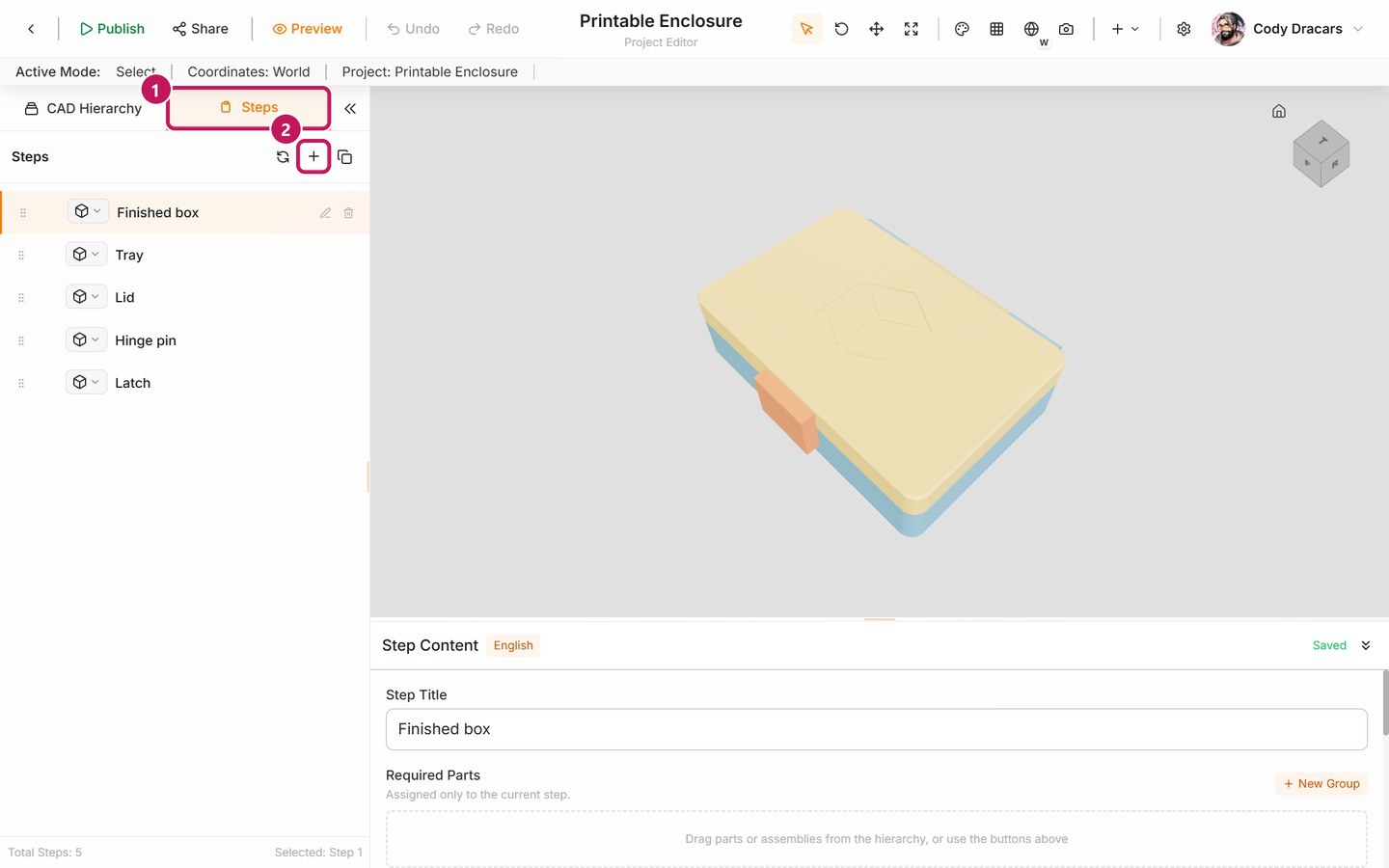
- (1) Open Steps.
- (2) Select Add manual item.
Reuse a step
When the next step shows the same assembly from the same angle, there's no need to start over. Copy the current one instead:
- Select the step, then select Duplicate selected step beside Add manual item.
- Give the copy a title.
- Choose whether to copy its Text and Indicators.
- Select Duplicate.
The copy keeps the original's part visibility and camera, and lands directly after it in the list.
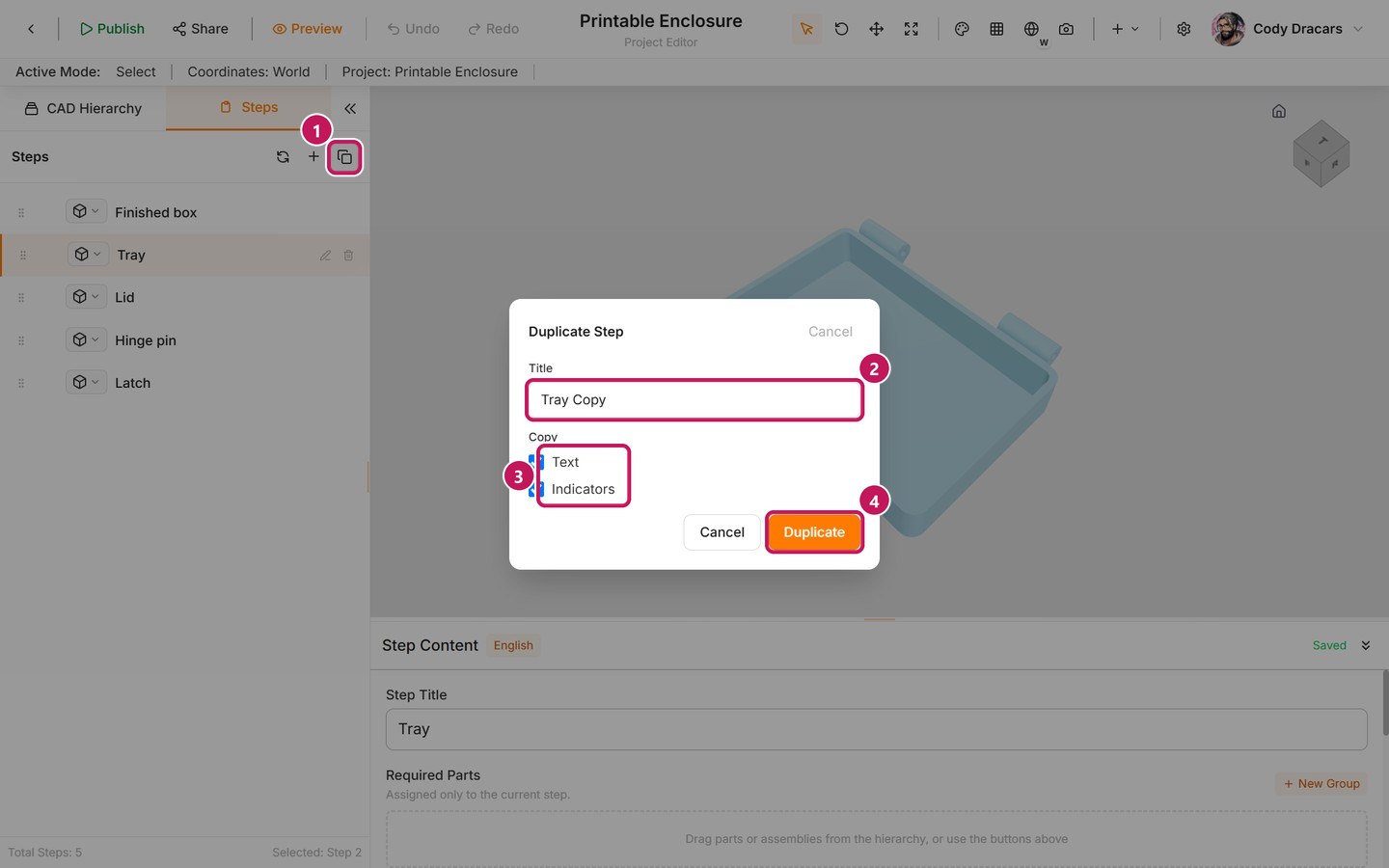
- (1) Duplicate selected step.
- (2) The title for the copy.
- (3) The Text and Indicators options.
- (4) Duplicate.
Reorder steps
Drag a step by the handle at the start of its row. If you prefer the keyboard, focus the handle and press the Up or Down arrow key. To remove a step, use Delete Step on its row. Deleted one by mistake? Undo in the toolbar (Ctrl+Z) brings it back.
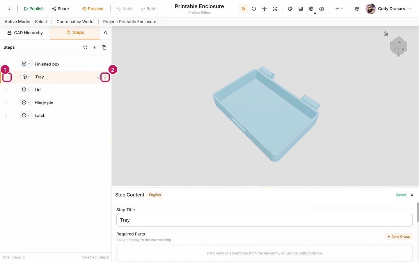
- (1) The handle, which starts a drag.
- (2) Delete Step, which shows up when you hover over or select a row.
Organize the procedure
Sections are a paid feature. Requires a Professional or Commercial plan. On Hobbyist, the same advice applies to step order and step titles.
Use sections for the real phases of the work, such as preparation, assembly, inspection, or maintenance. Keep the steps in the order an end user should actually do them, and give each one a short, descriptive title so the procedure is easy to scan.
Start with the smallest outline that works, then add detail as the procedure takes shape. A good section helps an end user answer "where am I in the job?" If it only exists to break up a long list, it probably isn't needed.
Write the instruction
Each step should get across one action or one thing to notice. A few habits help:
- Put the important verb first.
- Name the part involved.
- Say what tells the end user the step is done.
For example, "Install the cover and tighten the two marked screws" is far more useful than "Cover installation." Then use the 3D view to back the instruction up with the assembly state shown on that step.
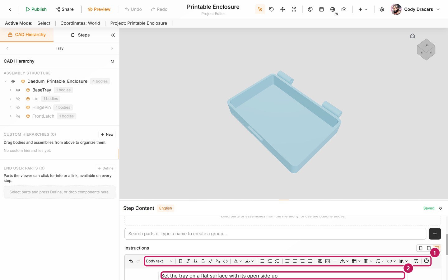
Scroll Step Content down to Instructions:
- (1) The toolbar formats the text and can link to a part.
- (2) The text area is where you write the action.
Set the assembly view
Select the parts that matter and arrange the view so the end user can see the work area. The view should support what the instruction says. Hide unrelated parts when they compete for attention, but keep enough around them that the end user can still get their bearings.
Click through the steps the way an end user would. Your text, ordering, and selected step are saved as you work. If the editor says it's still saving, let it finish before switching steps.
Show only what matters
When a crowded assembly makes a step hard to follow, use the assembly's Show/hide all control in CAD Hierarchy, then use Show for just the parts the end user needs. Select the relevant part too, so the instruction, the hierarchy, and the model all point at the same thing.
You don't always need to show a part completely on its own. The goal is to make the next action impossible to miss, and a bit of context usually helps with that.
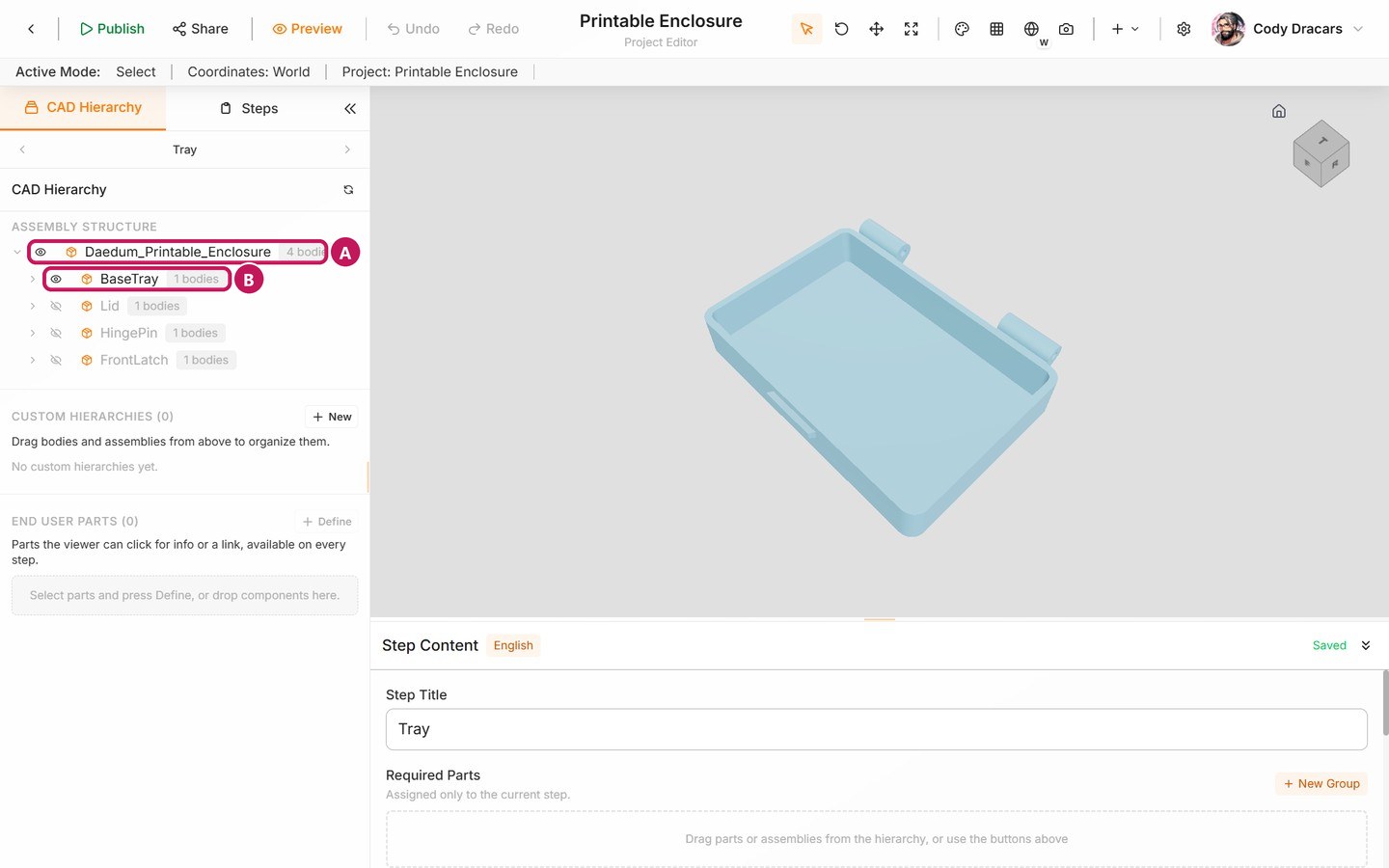
- (A) The eye at the start of the assembly row is Show/hide all.
- (B) The eye on a part row shows or hides just that part. Here, only
BaseTrayis showing.
Frame and orient the view
Use the 3D controls to get a clear look at the work area: drag to rotate, right-drag to pan, and scroll to zoom. When several steps cover the same area, keep the camera consistent, and only change the angle when a different view explains the next action better.
Each step remembers its own camera. To save the view end users open on:
- Select Set Initial Camera in the toolbar (
Ctrl+Alt+C). - Adjust the view if you need to.
- Select Save Camera.
The home button at the top right of the 3D view always takes you back to the step's saved camera. A new step doesn't inherit the previous step's view, which is one more good reason to duplicate a step when the angle should stay the same.
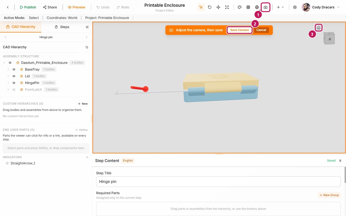
- (1) Set Initial Camera starts the mode, and an orange frame appears around the 3D view.
- (2) Save Camera keeps the new view. Select Cancel instead to keep the old one.
- (3) The home button returns to the saved camera.
Move a part
Hiding and showing parts isn't the only way to explain a step. To show a part before it's fitted, move it:
- Select the part in CAD Hierarchy or in the 3D view.
- Select Move Mode in the toolbar (
T). Three arrows appear on the part, one for each direction. - Drag an arrow to slide the part that way.
Rotate Mode (R) and Scale Mode (S) work the same way, and Select Mode (V) takes you back to normal selection. While a part is selected, the Properties panel has Reset Selected to put it back where it was. Don't worry about other steps: a moved part only stays moved in the step where you moved it.
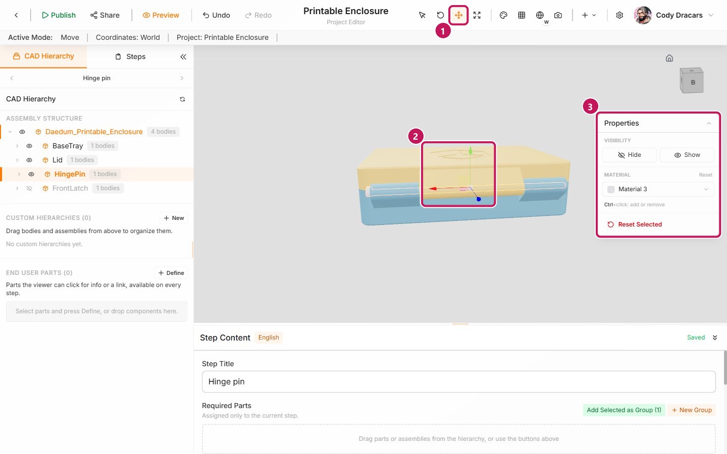
- (1) Move Mode.
- (2) The three arrows on the selected part. The red one slides it along the pin.
- (3) The Properties panel, with Hide, Show, the part's material, and Reset Selected.
Add required parts
When an end user needs to find or pick out a particular part, add it to the step's Required Parts area. This makes it clear exactly which part the step is about. It doesn't replace a clear instruction or a good camera view, though.
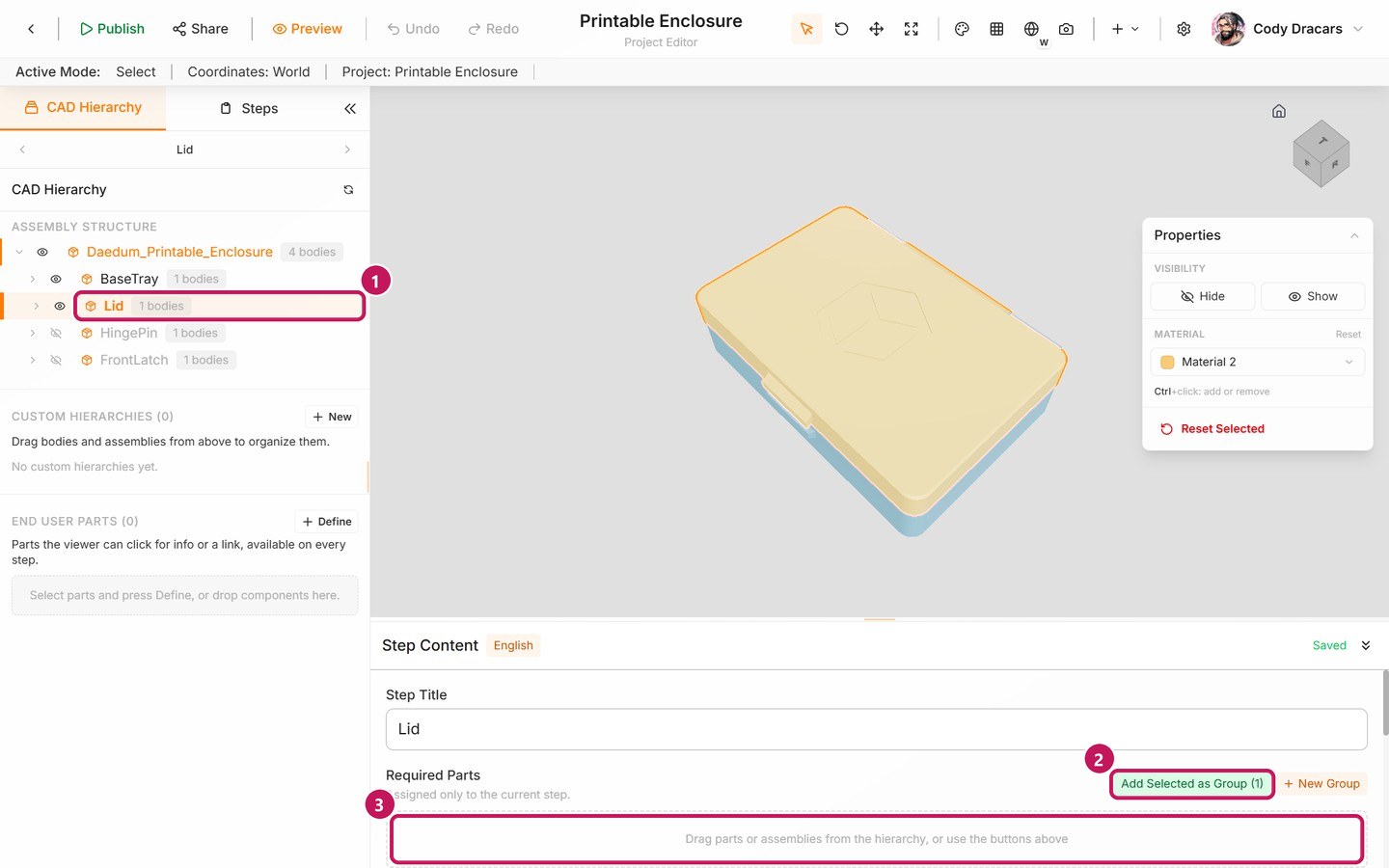
- (1) Select a part.
- (2) Then select Add Selected as Group.
- (3) Or drag it into the Required Parts area.
New Group creates an empty group you can fill in by name.
Required Parts is a list for one step. It's different from End User Parts, a separate hierarchy in CAD Hierarchy for building a catalog of parts an end user can buy or download. There's more on that in "Help end users source a part" further down this page.
Add visual guidance
When a part is hard to find, add a visual indicator, such as an arrow, from the editor toolbar. Place it where it supports the instruction, then preview the step to make sure it points at the right part from the end user's point of view.
Add Indicator opens the indicator menu:
- Straight Arrow for a direct target.
- Curved Arrow when the target needs a longer path.
- Edit Indicators to adjust ones you have already placed.
To place an arrow:
- Choose Straight Arrow from the menu. A bar at the top of the 3D view reads Click to place. Press
Escif you want to cancel. - Click the spot on the model the arrow should point at. The arrow points into the surface you click, so clicking the flat end of a pin gives you an arrow along the pin.
- The arrow shows up under Indicators in CAD Hierarchy. Select it there to change its color, Re-place Indicator, or Delete Indicator.
- With the arrow selected, use Scale Mode to resize it, Rotate Mode to turn it if it landed at the wrong angle, and Move Mode to pull it clear of the part.
The two pictures below show the menu first, then the finished step: the hinge pin pulled out of its knuckles, with an arrow showing which way it slides in.
The same menu also has an Indicator Library link. It opens your account library in a new tab, where you can import your own tool and prop models from STEP files and reuse them as indicators in any manual. Placing a custom indicator needs Professional or higher, but everyone can browse the library and its built-in presets.
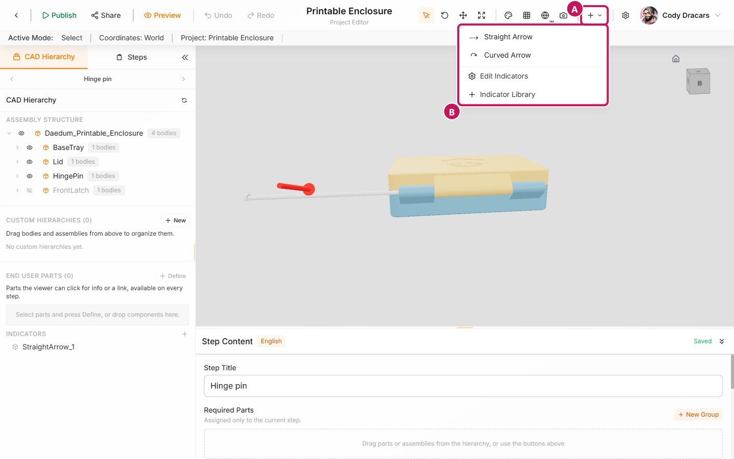
- (A) The Add Indicator control.
- (B) The menu it opens.
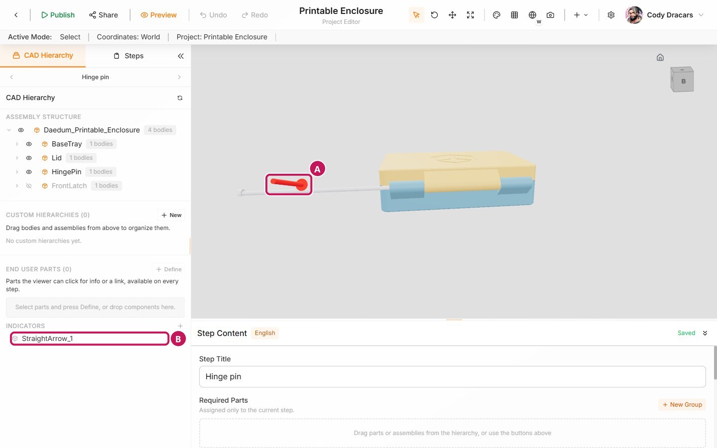
- (A) The placed arrow.
- (B) Its entry under Indicators in CAD Hierarchy.
When the model needs more context, the view controls can help:
- Rotate, pan, and zoom to show the work area.
- Turn on the grid when it helps explain orientation or placement (Show Grid, or press
G). - Set an initial camera when a step should open from a specific angle (
Ctrl+Alt+C). - Keep the coordinate setting the same throughout, unless a part's local orientation is genuinely useful.
All of these are optional. Start with the right parts showing and a clear instruction, and only add visual guidance when it solves a real problem for the end user.
Use other step and page types
On top of 3D Step, Image, Text, and Section (see Step types: 3D, Image, Text, and Section), the Steps panel has two more options for specific situations:
- 3D Dual Scene shows two assembly states on one step, with a toggle the end user can flip between them. It works well for a clear before and after, or two build options on the same step, and has its own toggle label.
- Title Page is a cover-style page with no instruction text. Use it to open a manual or a Section with a title and image instead of a procedure step.
You won't find these in the first Add manual item menu alongside the four main types. They show up as step type options once a step exists.
Work with materials
Select the Materials icon (a palette) in the editor toolbar to open the Material Editor. Here you can give a part or region a color or material, separately from the step-by-step visibility you set elsewhere. Materials you create can be saved to a reusable library and linked across the parts and steps that use them, so changing one updates every part linked to it.
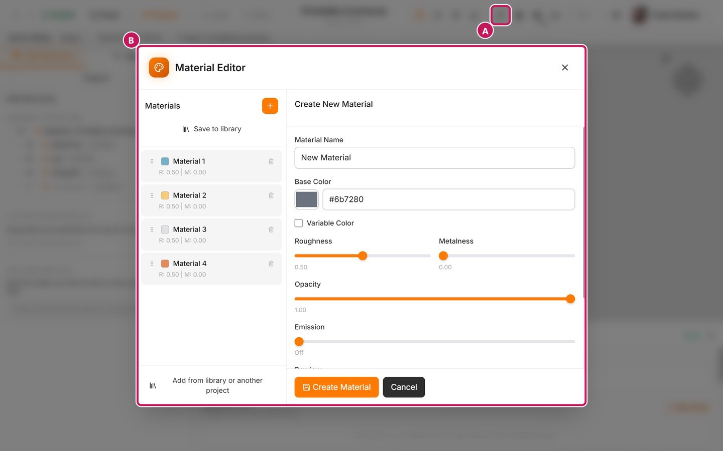
- (A) The Materials control.
- (B) The Material Editor it opens.
The list on the left holds the materials the model came with, and Save to library keeps one around for reuse.
Help end users source a part
CAD Hierarchy has its own End User Parts section for building a catalog of parts an end user might need to buy or download separately, like a replacement screw or a specific hinge. Give each part a name, a description, and a preview, and add a download or purchase link. Links to printables.com are recognized automatically and shown to end users as View on Printables, with the model's own preview and details.
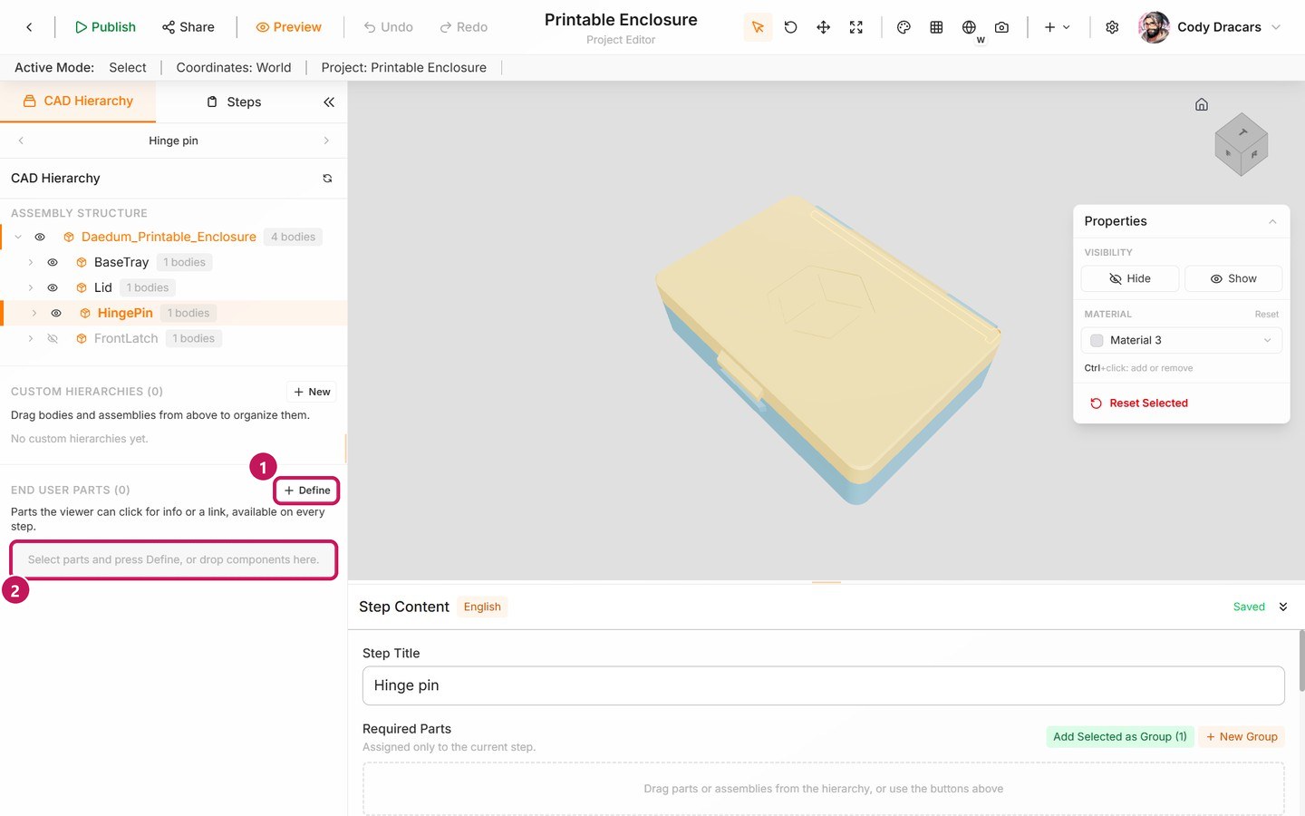
- (1) Select a part, then select Define.
- (2) Or drop it into the End User Parts area.
This is separate from the per-step Required Parts list above. Required Parts marks what an end user needs to find in one step, while End User Parts is a catalog for the whole manual of parts they can go and get.
Preview before publishing
Select Preview (Ctrl+Alt+P) to see the manual the way an end user will, rather than from the authoring view. Desktop, Tablet, and Phone above the preview switch the screen size.
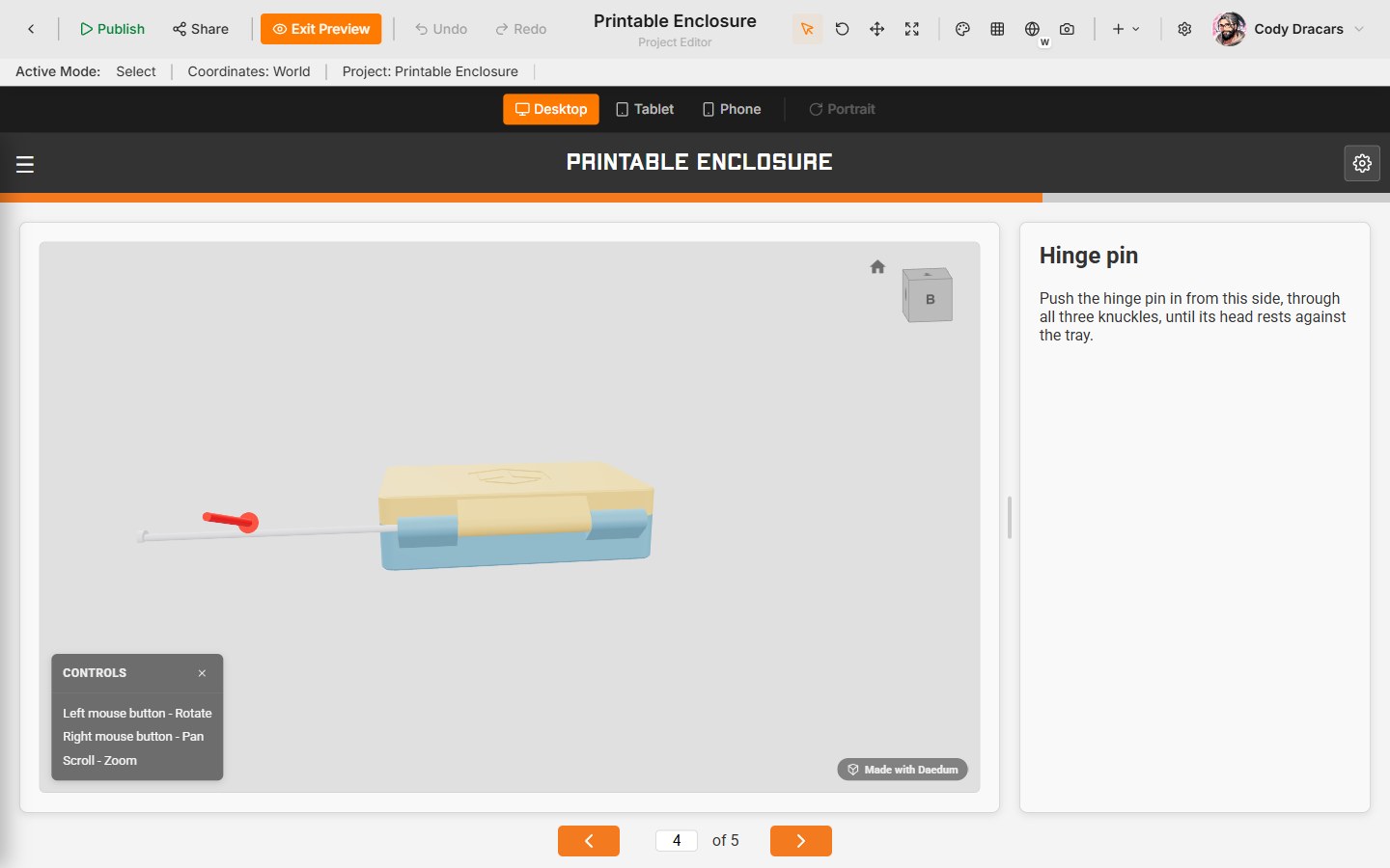
While you click through, look out for:
- Steps that assume the end user knows something they don't.
- Views where the important part is hidden or hard to pick out.
- Sections that don't match the real order of the work.
- Instructions that pack in more than one action without a clear stopping point.
Keyboard shortcuts
Hover over any toolbar button and the editor shows its shortcut. The keys below follow your own preset when you're signed in, and Daedum Default when you're not. You can change any of them under Keyboard shortcuts in your account; Controls, shortcuts, and snapping explains the presets.
| Action | Shortcut |
|---|---|
| Undo | Ctrl+Z |
| Redo | Ctrl+Shift+Z |
| Save | Ctrl+S |
| Copy step | Ctrl+C |
| Paste step | Ctrl+V |
| Preview the manual | Ctrl+Alt+P |
| Open the Publish dialog | Ctrl+Alt+Shift+P |
| Select Mode | V |
| Move Mode | T |
| Rotate Mode | R |
| Scale Mode | S |
| Deselect | Esc |
| Fit the camera to the model | F |
| Reset the selected parts | Alt+R |
| Reset everything in the step | Alt+Shift+R |
| Show or hide the grid | G |
| Set the step's initial camera | Ctrl+Alt+C |
| Indicator point snap | 1 |
| Indicator body snap | 2 |
| Cancel placing an indicator | Esc |
A few are held while you click, instead of pressed on their own:
| Hold while clicking to… | Hold |
|---|---|
| Add or remove parts from the selection | Ctrl |
| Select one body instead of its component | Alt |
| Select one color region of a body | Shift |
Once the procedure reads cleanly from start to finish, carry on with Publish, version, and embed.